VISIO TIPS HIDING PARTS OF A SHAPE ON DEMAND USING SHAPE GEOMETRY
When you’re designing a smart shape for Microsoft Visio, you’ll often want the user to influence the behavior of the shape through actions in the shape’s context menu. Creating context menu actions in Visio was explained in a previous post. This time, we want to create an action that shows or hides part of a single shape (no grouping allowed!).
When you’re designing a smart shape for Microsoft Visio, you’ll often want the user to influence the behavior of the shape through actions in the shape’s context menu. Creating context menu actions in Visio was explained in a previous post. This time, we want to create an action that shows or hides part of a single shape (no grouping allowed!).
And that’s exactly where the difficulty lies. When creating complex shapes, you’ll often find yourself grouping shapes and showing or hiding subshapes on demand. While this is fine, it creates extra complexity and when the user wanst to change the textual content of your shape, he’ll need to click the correct subshape to do so or things go wrong. That’s why it can be much nicer to do everything in a single, atomic shape.
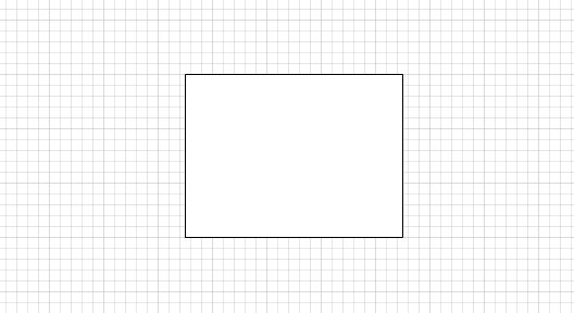
The trick to showing or hiding part of a shape lies in using the Geometry sections in the Visio Shapesheet. In this example, we’ll create a panel with an optional header. A context menu action will allow the user to show or hide the header. So, we’ll start with simple rectangle:
Calling up the Shapesheet requires enabling the developer ribbon. In the Shapesheet, we’ll add a user-defined cell called hasHeader with a value of FALSE. We’ll then add an Actions section (using the Insert button in the developer ribbon with the Shapesheet open). In it, we create a single action called setHeader with the following values:
- Action:
=SETF(GetRef(User.hasHeader),NOT(User.hasHeader)) - Menu:
Header - Check:
User.hasHeader
A new action called Header now appears in the shape’s context menu, with a check mark next to it when the value of User.hasHeader is true. When clicked, it toggles the value of User.hasHeader.
So far so good; now to create a header strip. In the Shapesheet, you’ll find a section named Geometry 1:
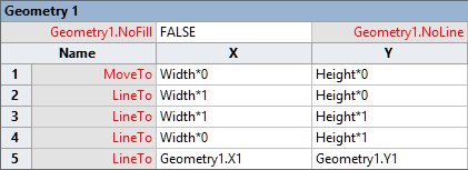
This section actually contains precisely the instructions necessary to draw the rectangle we have so far. A virtual pen is moved to coordinates (0,0). It then draws a line to (Width, 0), then a line to (Width, Height) and so on, until the rectangle is done. You will note that all coordinates are defined in terms of the shape’s Width and Height as defined in the Shapesheet’s Shape Transform section at the top of the Shapesheet. It is possible to change the drawing instructions, or add some more, to draw a different shape. In fact, for starters we’ll do just that to create a rectangle with rounded corners at the top. It’s interesting to note that this is something you will actually need to do in the Shapesheet’s Geometry section, as changing the border rounding in the Shape Format dialog will change the rounding of all corners.
By adding two drawing instructions (right-click a row and select Add row after), we change the shape geometry to this:
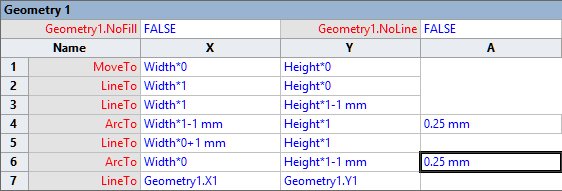
We’ve added two ArcTo instructions which create rounded corners of 1mm with a radius of 0.25mm. Also, some of the lines stop just 1mm short of the shape’s corner to accommodate the arcs.
Now where to draw the header panel? There are two approaches to this. First, we could add additional drawing instructions to the Geometry 1 section and define them in such a way, using IF instructions, that they don’t appear (or do nothing) when the header is not shown. Alternatively, we could add an additional Geometry section. We’ll pick the latter option.
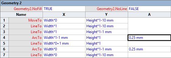
Using the developer ribbon’s Insert button, insert a new Geometry section. It will appear as Geometry 2. Initially, it will contain one move instruction and one line instruction that don’t do anything. We’ll add new instructions that draw our header strip:
A new header strip now appears on your shape:
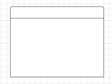
Please note that we have hard-coded the height of the header strip to 10mm in this example. You could also make it relative to the height of the shape itself by using a fraction of Height rather than 10mm. The same argument holds for the radius of the rounded corners, of course.
We can now return to our original task: making a header strip that can be shown or hidden on demand. We already have a user-defined cell called hasHeader for this purpose. Now it’s possible to turn the entire Geometry 2 section on or off by changing its NoLine property. We’ll set it to the formula =NOT(User.hasHeader). And there it is: the header can now be toggled through the shape’s context menu.
Of course, the header strip now has the same fill color of the shape. And that’s a problem, because a shape can only have one fill color, which is one reason why you would need to use groups to allow for multiple colors. Still, there is a trick we can use. We’ll set the rectangle’s main shape to have no fill, and use the shape’s general fill color for the header strip. This can be done by setting Geometry1.NoFill to true.
Happy developing!