In the last section of this tutorial for writing your own boot loader for a toy operating system, we had put together a first-stage boot loader that manages to find on disk and load a second-stage boot loader, which at this point simply prints “Hello, world” on the screen.
For the boot loader, this was one of the major hurdles. The first-stage boot loader will always have to be small enough to fit in about 450 bytes of code, and that’s simply not enough to do all we need to do to load our future kernel. Since there is no limit to the second stage boot loader’s size, we now have the space to do whatever we need to do to launch our kernel.
There is, in fact quite a lot to do still. The main challenge that we face in our second-stage boot loader is switching the CPU to the so-called protected mode. This is essential for modern operating systems. In the following sections, we will discuss what protected mode is and why we want to use it. This part is going to be a bit heavy on the theory, but it will be a necessary foundation for our next steps.
This article is part of a series on toy operating system development.
The CPU and Memory
You see, what it all boils down to is a legacy from the old days of computing. To get started, we’ll take a look at Intel’s first CPU (Central Processing Unit) or simply processor. In fact, we’ll start at the very beginning and look at the basics of computer memory – the transistor. Those looking for a quick fix to switch to protected mode might as well skip to the next part of this tutorial, but if you’re interested, bear with me, for you may learn a few things that help understand why things work the way they work, which will be immensely useful when you start building your future kernel.
A memory cell
All computer memory is centered about its simplest element: the data bit. One bit of data can have two values: zero or one. Or on or off. In fact, a data bit is much like a light switch. You turn the light on with the switch, and it stays on, until you turn it off. It doesn’t turn on or off by itself but requires that you flip the switch. In computer memory, you don’t actually use your finger to switch a data bit on or off (although there have been computers that required this), but you send an electrical current that changes that status of a switch.
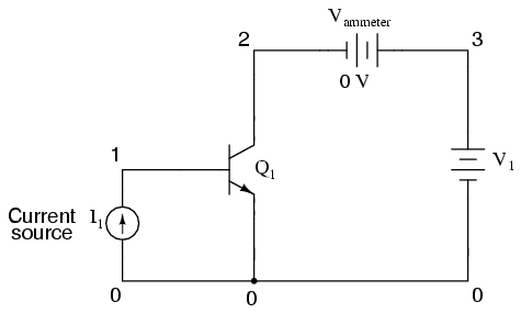
Such switches directed by current have been built as relays, where the current causes a little hammer to hit a lever, but modern computers (as in, over the last 50 years) use transistor switches. These have two advantages: they contain no mechanical components (no little hammers) and they can be made really, really small. After all, modern computer memory consists of an awful number of bits. A transistor switch is shown below. When an electrical current is placed on pin 1, there will be a current flow between pins 2 and 3. When the current is removed from pin 1, then the current will no longer flow between pins 2 and 3.
As a child I had an electronics kit that contained one or two transistors that you could use to build a circuit that would switch a light on. The kit manual had these diagrams that explained how it worked, but I found putting the circuit together much more fun than actually understanding the diagrams, which is why I am not now an electronics engineer.
In real computer memory, the transistor is combined with a few more exotic components to form a memory cell. For our purposes, we can really consider a memory cell to be a black box with three pins: input, output and select. It retains the idea of the transistor. There’s always a electrical current flowing through the input pin (if you turn your computer off, the memory contents are lost) and if you place a current on the select pin, you can change whether the output pin produces an electrical current or not.
The presence of an electrical current at the output pin means that the memory cell has a value of 1. The absence of the current means a value of 0. And this is where we leave the realm of electronic engineering, fortunately.
Many memory cells
One memory cell allows us to store one bit of data, just like a light switch. That’s not a lot – it would be nicer if we had two. Two cells allow us to store two bits of data, and that means we can store the values 0, 1, 2 and 3. This is because there are four different ways we can set the values of our two cells: off-off, off-on, on-off and on-on. If we had three cells, we would be able to store the values 0, 1, 2, 3, 4, 5, 6 and 7, because the cells can be set to:
| Cell 2 | Cell 1 | Cell 0 | Total value |
|---|---|---|---|
| off | off | off | 0 |
| off | off | on | 1 |
| off | on | off | 2 |
| off | on | on | 3 |
| on | off | off | 4 |
| on | off | on | 5 |
| on | on | off | 6 |
| on | on | on | 7 |
Of course this goes on. If we had eight cells, we could store values between 0 and 255 (there are 2^8 possibilities to set the cells). This range of values represented by 8 cells is actually called a byte. With 16 cells, we can store values between 0 and 65535 (or 2^16-1), and this is called a word. (Naturally we can also store two bytes rather than a single word – that’s up to us.) Here are some other terms for groups of bits:
| Term | Number of bits | Value range |
|---|---|---|
| Nibble | 4 | 0-15 (2^4) |
| Byte | 8 | 0-255 (2^8) |
| Word | 16 | 0-65,535 (2^16) |
| Double word (dword) | 32 | 0-4,294,967,295 (2^32) |
| Quad word (qword) | 64 | 0-18,446,744,073,709,551,615 (2^64) |
Of course, being able to store a single number is still not near to what we’ve come to expect from modern computer memory. In fact, engineers have been able to stick an awful amount of memory cells on a single memory chip. Consider a memory chip for 1 gigabyte: it contains 8 x 1024 x 1024 x 1024 cells, which is 8,589,934,592 cells, all wired together in such a smart way that the whole chip is the size of a cigarette lighter.
Beyond the mind-boggling smallness of all this, it raises another question: how do you actually flip the state of a single memory cell? Are there 8 billion little wires sticking out of the chip? Actually, no. There are only 20 or so wires.
Addressing
Imagine a memory chip with 1,048,576 memory cells on it. That’s one megabit (1 Mb) of memory, or 128 KB. It would look like this:

That’s more than a million individual memory cells, and we need a way to talk a single on of them. To make this possible, the memory chip engineers have thoughtfully attached 20 wires called address pins. By placing a voltage on a combination of these pins, we can tell the memory chip which cell we would like to talk to. The current value of that cell is then placed on the data pin.
The combination of currents placed on the address pin is coded just like we code a group of memory cells: it’s a binary value.
- To address cell #0, we leave all address pins off (value 0).
- To address cell #1, we place a current on address pin #0 (value 1).
- To address cell #3, we place a current on address pins #0 and #1 together (value 3).
- To address cell #57, we place a current on address pins #0, #4, #5, and #6 (value 57, or binary 111001).
- In address the very last cell (#1,048,575), we place a current on all address pins (value 1,048,575, or binary 1111 1111 1111 1111 1111).
Of course, this is just for reading. In reality, there is yet another pin that allows us to indicate whether we want to retrieve the current value of the memory cell from the data pin (read), or whether we want the current placed on the data pin to be stored in the addressed cell (write).
Access speed
In theory, this is how memory chips work. In practice, however, there are a lot of snags that have to do with speed. Reading or writing a bit is quite fast (say 80 nanoseconds), but in order to read or write any realistic value (say a number between 0 and 255), we would have to perform 8 memory accesses, which is 640 nanoseconds. That sounds really fast, but it adds up. We do a lot of reading and writing to the computer memory, so we need this to be really fast. This is why in modern computer memory, we always access an entire byte or word at the same time.
In a real chip, there would actually be 8 lines for the data pin (in order to be able to retrieve an entire byte of data). And this is exactly what you get in an Intel 8088 microprocessor. There’s another upside to this: since we now access 8-bit groups of memory cells, we can actually address eight times more memory as well. With the same 20 address lines, we can access one megabyte rather than one megabit. With Intel’s 8086 processor, things got faster still: it actually had 16 data pins, which allow us to read or write 16 bits (one word) of data at a time.
Real Mode Segmented addressing
Sounds good so far? Because this is exactly where it gets hairy. Although there are 20 address lines available that theoretically should allow the 8088 processor to access 1 megabyte of memory, that’s not actually how it works. You see, the CPU itself doesn’t think in terms of 20 bit numbers, required for the address lines. Rather, it works with 16-bit quantities. And with a 16-bit number, we can access values between 0 and 65535 (64KB) only, which is far short of one megabyte. Actually, is 16 times less, which will become important in a moment.
Still, it’s possible to access the entire memory. Since 20-bit addresses can’t be squeezed in 16-bit values, this actually done using two 16-bit values: a segment and an offset. The segment is the start of a window in memory, specified using a 16-byte granularity. Therefore:
| Segment | Real address |
|---|---|
| 0 | 0 |
| 1 | 16 |
| 2 | 32 |
| 3 | 48 |
| … | … |
| 65,533 | 1,048,528 |
| 65,534 | 1,048,544 |
| 65,535 | 1,048,560 |
What the segments are actually doing is addressing so-called paragraphs of memory, which are 16-byte chunks. With this trick, the addressable space has just been increased 16-fold, which means we can one again address the full megabyte – but there is something missing. While we can address the bytes that live at addresses 0, 16, 32, 48 etc., we have no way of getting to addresses 1..15, 17..31, 48..63 etc.
This is where the offset comes in. The 16-bit offset value is the byte to be addressed within a segment. This means that the real byte being addressed lives at address segment * 16 + offset.
| Segment | Offset | Real address |
|---|---|---|
| 0 | 0 | 0 |
| 0 | 5 | 5 |
| 1 | 7 | 1 * 16 + 7 = 23 |
| 65,534 | 2 | 65,534 * 16 + 2 = 1,048,546 |
And voilá! We now have a way of addressing the full memory space. This processor mode and memory model is actually called real mode. Still, there is something fishy about this. As it turns out, it is possible to address the same byte in many different ways. Consider:
| Segment | Offset | Real address |
|---|---|---|
| 1 | 50 | 66 |
| 2 | 34 | 66 |
| 3 | 18 | 66 |
| 4 | 2 | 66 |
The four different segment/offset combinations above all address the same byte in memory. Just is just the way things work. It’s one of the small irritations that protected mode actually corrects, and we’ll get to that very soon.
More memory
The above discussion has centered around a memory chip of one megabyte. This used to be a lot of memory, but these days it’s peanuts. At the time, Bill Gates reportedly said “640 KB should be enough for everybody.” (He didn’t actually say this), but these days a couple of gigabytes of memory is the standard. Clearly, 20 address lines aren’t enough to address all that memory and there was a time when you had to install particular software to address your precious 4 MB or 16 MB of memory (DOS4GW, for example).
However, when Intel released its 80386 processor this was a thing of the past. A range of 4GB of memory was now supported (potentially – no one had that much) and it was done using wider register – CPUs now worked with 32-bit numbers and a 32-bit value can actually hold a 4GB memory address.
So problem solved? Not quite. While the folks at Intel provided us with wider registers, they also provided us with much more: the protected mode. I will have much more to say about that in the next section. For now, suffice it to say that in order to actually address more than 1 MB of memory, you need to switch the processor to protected mode and that’s actually a tricky thing to do.
Why talk about real mode?
This was quite a long article discussing things that are no more. No modern operating system will operate in real mode, and no-one uses segmented addressing. Or do they? In fact, there are times when there is no getting away from it. In particular, when any Intel CPU first starts, it starts off in 16-bit real mode. The BIOS code is written in real mode. Your boot loader code must be written in real mode. Only when you actually switch to protected mode are you free from it.