In the previous section of this tutorial for writing your own toy operating system, we discussed the 8088/8086 processor’s real mode memory addressing system, only to conclude that we really should leave this mode and enter protected mode, which brings us many benefits. What these benefits are will be discussed below.
This is not to say we don’t need a good understanding of real mode, since this is the mode that all Intel processors start up in. Our entire boot sector code has been written in real mode 16-bit assembly code!
This article is part of a series on toy operating system development.
What protected mode is
As shown in the previous article, in real mode we can access exactly one megabyte of memory, which is very little by today’s standards. The memory addressing system is segmented, that is, we need to combine segment and offset values to specify a memory address.
In protected mode:
- We can address 4GB of memory
- Memory addresses are specified using a flat model, without segmentation
- We can specify which memory areas a process can write to, and detect when it tries to write somewhere else (which is why the whole thing is called “protected mode”)
- Our kernel code can run with a higher privilege level than other processes, thus performing operations that ordinary processes should not be able to perform
At a glance, the 4GB address space seems like the very thing we are looking for, but the protection that this processor mode offers is actually even more important. In days gone by, all memory was shared between all processes running and there was no protection. If a program inadvertently overwrote a section of memory used by another program (or the kernel), when the whole system would crash. What protected mode accomplishes is that when a process tries to write to memory is isn’t supposed to, the processor will detect this and notify the kernel. The kernel can then terminate the misbehaving process.
With these features, Intel has actually provided operating system developers with the hardware tools they need to write stable operating systems!
Memory addressing in protected mode
Protected mode actually still uses segments, but in a very different way. Instead of accessing a segment/offset pair directly, as you would do in real mode programming, in protected mode the processor is loaded with a table of selectors which are mapped to a section of memory. If such a selector is mapped to the entire memory (4GB), then we can access this memory as a flat memory space with a 32-bit index. A 32-bits number is between 0 and 4,294,967,295, which is precisely 4GB – problem solved!
Since the processor has a table of selectors, we can actually create selectors for smaller memory areas. The upshot of this is protection. Consider what happens when the kernel launches a process:
- The kernel selects an area of memory for the process, say 1 MB of memory mapped somewhere the kernel finds convenient.
- The kernel creates a selector for this memory area, configures it with the start and size of the memory area, and adds it to the list of selectors maintained by the processor.
- The kernel sets the selector it just created as “active”.
- The kernel loads the program code into the memory area referenced by the selector and transfers control to the process.
- The process tries to write to a memory address not included in the selector’s memory range. Since the processor know which memory belongs to the selector and which memory doesn’t, it intervenes and lets the kernel know that there was a memory access violation, using a mechanism known as an interrupt (we’ll get to that).
- The kernel does whatever is needs to do to stop the process.
That’s it – our kernel is now actively helped by the CPU to deal with naughty processes, resulting in a stable system.
The Global Descriptor Table
The list of selectors that the processor uses is not actually kept inside the processor. Instead, it’s kept somewhere in memory (in an area carefully guarded by our kernel) and our code let’s the CPU know at some point where to find it. This is in fact a required step for getting into protected mode. This list of selectors in memory is called the global descriptor table (GDT) and it must carefully follow a specific format.
Please note that everything we are going to discuss in the remainder of this tutorial is for the 80386+ processor. The 80286 processor had a protected node which was slightly different. We will ignore it entirely.
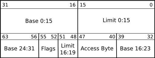
The diagram shown here illustrates that a descriptor occupies a space of 64 bits, or 8 bytes. The information in it must be stored just so, or the processor will not understand it. The information we need is:
| Offset (bits) | Name | Meaning |
|---|---|---|
| 0..15 | Limit | Lower 4 bytes of the descriptor’s limit |
| 16..31 | Base | Lower 4 bytes of the descriptor’s base address |
| 32..39 | Base | Middle 2 bytes of the descriptor’s base address |
| 40..47 | Access byte | A group of bit flags defining who has access to the memory referenced by this descriptor |
| 48..51 | Limit | Upper 4 bits of the descriptor’s limit |
| 52..55 | Flags | Four flags influencing segment size |
| 56..63 | Base | Upper 2 bytes of the descriptor’s base address |
The information in a descriptor is smeared out in a fancy way to make it all fit in precisely 8 bytes, and in just the way the processor wants it. We’ll just have to make sure we get it right.
- Base address – This is the address where the block of memory that the descriptor references starts. This is a 32-bit value, sadly spread out over three different areas in the descriptor – but nothing some bitshifting can’t solve. Being a 32-bit value, it’s big enough to indicate any starting address in the 4GB range.
- Limit – This is the size of the memory block that the descriptor references. There are only 20 bits available for this value, meaning that we can only address 1 MB of memory. However, we can enable so-called page granularity which results in our value being multiplied by 4,096, which equals once again 4GB. Needless to say, we want this.
The access byte and flags are structured like this:

| Bit | Name | Description |
|---|---|---|
| Pr | Present | Selectors can be marked as “not present” so they can’t be used. Normally, set it to 1. |
| Privl | Privilege level | There are four privilege levels of which only levels 0 and 3 are relevant to us. Code running at level 0 (kernel code) has full privileges to all processor instructions, while code with level 3 has access to a limited set (user programs). This is relevant when the memory referenced by the descriptor contains executable code. |
| Ex | Executable | If set to 1, the contents of the memory area are executable code. If 0, the memory contains data that cannot be executed. |
| DC | Direction (code segments) | A value of 1 indicates that the code can be executed from a lower privilege level. If 0, the code can only be executed from the privilege level indicated in the Privl flag. |
| DC | Conforming (data segments) | A value of 1 indicates that the segment grows down, while a value of 0 indicates that it grows up. If a segment grows down, then the offset has to be greater than the base. You would normally set this to 0. |
| RW | Readable (code segments) | If set to 1, then the contents of the memory can be read. It is never allowed to write to a code segment. |
| RW | Writable (data segments) | If set to 1, then the contents of the memory can be written to. It is always allowed to read from a data segment. |
| Ac | Accessed | The CPU will set this to 1 when the segment is accessed. Initially, set to 0. |
| Gr | Granularity | For a value of 0, the descriptor’s limit is specified in bytes. For a value of 1, it is specified in blocks (pages) of 4 KB. This is what you would normally want if you want to access the full 4GB of memory. |
| Sz | Size | If set to 0, then the selector defines 16-bit protected mode (80286-style). A value of 1 defines 32-bit protected mode. This is what we want. |
All that sounds complicated, but it isn’t really. Most of the flags have standard values that you would not normally change and we are not going to define all that many segments (in fact, only 3). The trick really lies in writing code that puts the right bits in the right location, and telling the CPU where the table of descriptors lives.
What descriptors do we need?
For our kernel, we only need three descriptors:
- A NULL-descriptor (an empty descriptor that is required to exist)
- A 4GB code scriptor
- A 4GB data descriptor
The kernel, after all, will need access to the entire available memory. Only later, when we are ready to start running processes, will we be interested in creating descriptors for smaller memory areas.
The NULL-descriptor
The NULL-descriptor is simply 8 empty bytes. No trick to it.
The code descriptor
The code descriptor should be configured like this:
- Base address = 0x0
- Limit = 0xffff (with page granularity turned on, this is actually 4GB)
- Access byte
- Present = 1
- Privilege level = 0 (privilege level 0 is for kernel code)
- Executable = 1 (this is a code segment)
- Direction = 0
- Readable = 1 Combining all these bits gets us the value 1001 1010b, or 0x9a.
- Flags
- Granularity = 1 (for 4KB pages)
- Size = 1 (32-bit style) Combining all these bits gets us the value 1100 1111b, or 0xcf.
The data descriptor
The data descriptor should be configured like this:
- Base address = 0x0
- Limit = 0xffff (with page granularity turned on, this is actually 4GB)
- Access byte
- Present = 1
- Privilege level = 0 (privilege level 0 is for kernel code)
- Executable = 0 (this is a data segment)
- Conforming = 0
- Writable = 1 Combining all these bits get us the value 1001 0010b, or 0x92.
- Flags
- Granularity = 1 (for 4KB pages)
- Size = 1 (32-bit style) Combining all these bits get us the value 1100 1111b, or 0xcf.
Loading the Global Descriptor Table
Let’s say we have defined the global descriptor table in memory, containing 3 entries of exactly 8 bytes each, with the values presented above. Now how do we tell the processor about it? This is actually the simple bit. The processor offers a single instruction to load the GDT:
lgdt [gdt pointer]All we have to do is stick in the address (a special pointer structure) where we placed our table. Note that this instruction can be executed in real mode, before we actually jump to protected mode.
It’s time now to look at some code. Let’s setup a global descriptor table with three entries as above at address 0000:0800 (real mode segment and offset).
# Point es:di to the right memory section:
mov   ax, 0
mov   es, ax
mov   di, 0x800

# NULL Descriptor:
mov   cx, 4                         # Write the NULL descriptor,
rep   stosw                         # which is 4 zero-words.

# Code segment descriptor:
mov   es:[di],   word ptr 0xffff    # limit = 0xffff (since granularity
                                    # bit is set, this is 4 GB)
mov   es:[di+2], word ptr 0x0000    # base = 0x0000
mov   es:[di+4], byte ptr 0x0       # base
mov   es:[di+5], byte ptr 0x9a      # access = 0x9a (see above)
mov   es:[di+6], byte ptr 0xcf      # flags + limit = 0xcf (see above)
mov   es:[di+7], byte ptr 0x00      # base
add   di, 8

# Data segment descriptor:
mov   es:[di],   word ptr 0xffff    # limit = 0xffff (since granularity
                                    # bit is set, this is 4 GB)
mov   es:[di+2], word ptr 0x0000    # base = 0x0000
mov   es:[di+4], byte ptr 0x0       # base
mov   es:[di+5], byte ptr 0x92      # access = 0x92 (see above)
mov   es:[di+6], byte ptr 0xcf      # flags + limit = 0xcf (see above)
mov   es:[di+7], byte ptr 0x00      # base
Now to load the table with the lgdt instruction, we’ll need yet another structure: the pointer to the global descriptor table. This takes the following form:
| Field | Size | Description |
|---|---|---|
| Size | 2 bytes | Number of bytes (not entries) in the global descriptor table, minus one |
| Offset | 4 bytes | Linear address of global descriptor table |
There’s a fancy reason why the table size is actually its number of bytes minus one. The system designers decided that the maximum number of bytes in the table should be 65,536 (2^16), but two bytes can only hold values between 0 and 65,535. So you actually put in one less than the total, so that 0 means 1, 1 means 2, and so on. A consequence of this that it’s not possible to have a global descriptor table with zero entries in it.
Some assembly code for actually loading the table follows:
gdt:
.word  24    # Size of GDT in bytes minus 1
.int   0x800  # Linear address of GDT

load_gdt:
  lgdt gdt
That’s how it’s done. We have now informed the processor of the existence of our global descriptor table, and are one step closer to switching to protected code. It didn’t require a lot of complicated code – all we’ve done is created a set of values and used lgdt to tell the processor where it is.
Next steps
There is a reason we loaded our 3-entry GDT at 0000:0800 rather than simply at 0000:0000. That’s because we need those first 2048 bytes to load yet another structure: the global interrupt table (IDT). This will be the next thing we do, but it requires that we understand what an interrupt is and what it’s used for.